

Automotive Diagnostics: Ensuring Vehicle Safety
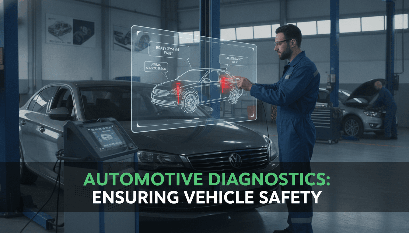
Modern vehicles are software systems on wheels. Understanding how diagnostic infrastructure works — and where it can fail — matters more than most engineering teams realise until something goes wrong.
What Does Automotive Diagnostics Actually Cover?
The term gets used loosely. In practice, it spans three distinct layers.
The first is on-board diagnostics (OBD). Since OBD-II became mandatory in the US in 1996 and EOBD in Europe in 2001, every passenger vehicle has exposed a standardised 16-pin diagnostic connector and a set of diagnostic trouble codes (DTCs). These codes follow SAE J1979 and ISO 15031 standards. They tell you a fault category, not root cause.
The second layer is ECU-level communication. Modern vehicles carry anywhere from 30 to over 100 electronic control units depending on the platform. These ECUs talk over CAN bus (ISO 11898), LIN, FlexRay, or increasingly, automotive Ethernet (100BASE-T1, as per IEEE 802.3bw). Each ECU has its own diagnostic services, defined in UDS (Unified Diagnostic Services, ISO 14229). UDS is where the real diagnostic depth lives — fault memory reads, ECU resets, software updates, and routine control all run through UDS session management.
The third layer is telematics and remote diagnostics. A telematics control unit (TCU) connects the vehicle to a backend over cellular (4G LTE or 5G). Fault data, sensor streams, and usage telemetry flow to cloud infrastructure continuously. This is where predictive diagnostics happens.
Most teams building fleet management or connected vehicle products interact with all three layers simultaneously.
How Do Diagnostic Trouble Codes Actually Work?
A DTC is a five-character alphanumeric code. The first character identifies the system: P for powertrain, C for chassis, B for body, U for network. The second character distinguishes whether the code is standardised (0) or manufacturer-specific (1, 2, or 3). Characters three through five narrow down the fault within that system.
When a fault is detected, the ECU sets a pending DTC. If the fault persists across two consecutive drive cycles, it becomes a confirmed DTC and lights the malfunction indicator lamp (MIL). Intermittent faults that self-resolve leave a history DTC behind, which the ECU eventually clears after a defined number of warm-up cycles without reoccurrence.
This behaviour is defined in ISO 15031-6. The nuance that trips up most software teams is that a cleared DTC does not mean a resolved fault. It means the ECU's readiness monitors passed a threshold. Confusing these two states has caused real diagnostic misses in the field.
| DTC State | MIL On? | Persists After Clear? | Indicates |
|---|---|---|---|
| Pending | No | No | Single-cycle fault detection |
| Confirmed | Yes | Yes (until cleared) | Repeated fault across drive cycles |
| History | No | Yes (limited cycles) | Past fault, no current trigger |
| Permanent | No | Yes (cannot be cleared manually) | EPA-mandated anti-tamper |
Permanent DTCs (defined in SAE J1979-DA) cannot be erased with a scan tool. They clear only when the ECU's own monitors verify the fault is gone. This was introduced to prevent emissions test fraud.
/// Not sure where to start?
Get the architecture before you commit
Tell us what you're building and we'll map the technical approach, stack, and rough timeline. No cost, no obligation, no sales call required.
Building a Telematics Pipeline for Predictive Diagnostics
Remote diagnostics at scale requires a well-designed data pipeline. The architecture typically looks like this:
The TCU collects CAN bus messages and periodically batches or streams them over MQTT or HTTPS to a cloud ingestion layer. At Sodio, we've seen teams underestimate the volume here. A single CAN bus running at 500 kbps can generate several hundred megabytes of raw data per vehicle per day if you're logging everything. You don't want to do that. Selective logging based on signal IDs, triggered captures on DTC events, and edge filtering on the TCU itself are standard techniques to keep data volumes sane.
On the backend, the ingestion layer feeds into a time-series store. InfluxDB, TimescaleDB, and AWS Timestream are common choices. The query patterns for diagnostic data (range queries, threshold alerts, trend analysis) fit time-series models well. Relational databases struggle here once you're past a few million data points per vehicle.
Signal Decoding and DBC Files
Raw CAN frames are just byte arrays. Decoding them into engineering values requires a DBC (database CAN) file, which maps frame IDs and bit positions to signal names, scales, offsets, and units. OEM DBC files are proprietary. For third-party applications, you're either reverse-engineering signals, working from partial public datasets, or negotiating access with the OEM.
Python's python-can and cantools libraries are the standard starting point for signal decoding in a backend service. For high-throughput scenarios, writing the decoder in Go or Rust with a compiled signal map is worth the extra build time.
Predictive Fault Models
Once you have clean signal data, predictive diagnostics uses time-series anomaly detection or supervised classification. A common starting point is training an isolation forest or LSTM-based model on pre-fault windows from historical data. The challenge is always label quality: vehicles rarely have clean ground-truth fault timestamps, so you end up working with DTC confirmation timestamps as a proxy, which introduces lag.
Production-grade predictive systems at major OEMs typically target 72 to 96 hours of advance warning for high-priority faults. Getting there requires feature engineering from multiple signals in combination, not just a single sensor reading.
What Are the Security Risks in Connected Vehicle Diagnostics?
Diagnostic interfaces are a significant attack surface. A remote attacker who can reach the UDS layer can issue ECU reset commands, read VIN and calibration data, or trigger actuator routines. The 2015 Jeep Cherokee remote hack (CVE-2015-5611) exploited a cellular-connected head unit to reach the CAN bus, demonstrating that this is not a theoretical concern.
UNECE WP.29 Regulation 155 (R155) became mandatory for new vehicle type approvals in Europe in July 2022, and for all new vehicles sold from July 2024. It requires OEMs to implement a certified Cyber Security Management System (CSMS). This directly impacts anyone building diagnostic tools or telematics hardware that connects to a vehicle's networks.
Practically, this means:
- Diagnostic sessions over UDS require security access (service 0x27), which involves a seed-key challenge. The algorithm is ECU-specific and typically not public.
- Over-the-air (OTA) software updates must be cryptographically signed. AUTOSAR Adaptive supports SecOC (Secure Onboard Communication) for this.
- Backend systems storing vehicle data must comply with GDPR if operating in Europe, and California's CCPA for US fleets.
If you're building a fleet diagnostics platform for a European market, R155 compliance is not optional. Build it in from the start.
Conclusion
Automotive diagnostics is a mature domain with well-defined standards, but the implementation details are genuinely complex. OBD-II and UDS give you the interfaces. Telematics pipelines give you scale. Predictive models give you lead time. Security and regulatory compliance give you legal cover.
The clearest next step if you're evaluating a diagnostic platform build: map your exact data sources first. Know which ECUs you need to reach, which bus protocol they use, and whether you have access to DBC files or UDS service descriptions. That scoping exercise will tell you more about project feasibility than any architecture diagram.
FAQ
What is the difference between OBD-II and UDS? OBD-II (ISO 15031 / SAE J1979) is a standardised emissions-focused diagnostic interface mandatory on all passenger vehicles since the mid-1990s. UDS (ISO 14229) is a broader ECU-level communication protocol used by OEMs for full diagnostics, ECU programming, and service routines. OBD-II is a subset of what UDS can do.
Can a third-party application read all vehicle data over OBD-II? No. OBD-II mandates access to emissions-related PIDs only. Manufacturer-specific data, ECU internals, and many sensor streams require proprietary UDS services and are gated behind security access algorithms that OEMs do not typically publish. Access depends on agreements with the OEM or reverse-engineering efforts.
How much data does a connected vehicle generate per day? It varies significantly by logging configuration. A fully instrumented vehicle logging all CAN traffic can produce hundreds of megabytes per day. Selective telemetry systems targeting specific signals and event-triggered captures typically reduce this to a few megabytes per vehicle per day, which is manageable at fleet scale.
What is a DBC file and why does it matter? A DBC file maps raw CAN frame IDs and byte positions to human-readable signal names with scaling and unit information. Without it, CAN data is uninterpretable bytes. OEM DBC files are proprietary and not publicly available, which creates real access barriers for third-party diagnostic tool developers.
Is UNECE R155 compliance required for diagnostic software providers? R155 primarily targets OEMs, requiring a certified CSMS. But software and hardware suppliers in the diagnostic chain are directly affected because OEMs must demonstrate that their entire supply chain meets cybersecurity requirements. If your product connects to a vehicle's network, you will need to demonstrate conformance as part of supplier qualification.
Have a project in mind? Contact Sodio Technologies to discuss your requirements and explore the right technology solution for your business.
/// Work with us
Talk to the engineers who'd build it
You'll get a technical scope, timeline and cost estimate from the people doing the work, not an account manager. In-house team, no subcontracting, since 2016.